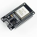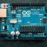

The ESP32 is a powerful and versatile microcontroller known for its built-in Wi-Fi and Bluetooth capabilities, making it a favorite for IoT projects. If you're coming from the Arduino world, you'll be pleased to know that setting up and programming the ESP32 is a very similar experience using the same IDE. This guide will take you from a fresh start to blinking your first LED.
Table of contents [Show]
Step 1: Install the Arduino IDE
If you don't already have it, the Arduino IDE is the first thing you need. It's the environment where you'll write and upload your code. You can download the latest version for your operating system (Windows, macOS, or Linux) from the official Arduino website.
- Download from: https://www.arduino.cc/en/Main/Software
- Recommendation: While both Arduino IDE 1.x and 2.x will work, some advanced plugins might still only be supported on version 1.x. If you're a beginner, either is fine.
After downloading, follow the installation instructions for your specific OS. Once installed, open the IDE to ensure it's working correctly.
Step 2: Install the USB to UART Bridge Driver
Most ESP32 boards use a USB-to-UART bridge chip (like the CP210x or CH340) to communicate with your computer. This driver is essential for your computer to recognize the ESP32 as a serial device.
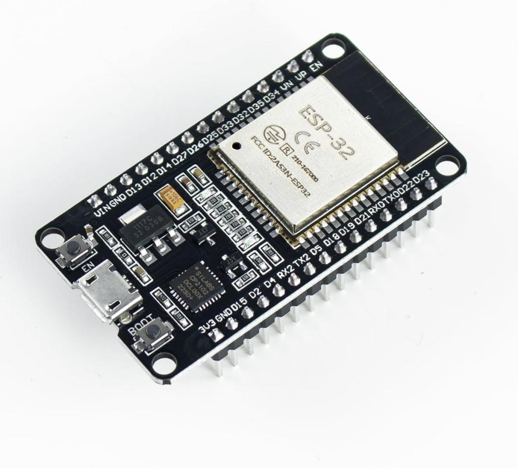
- How to check: Look for a small chip near the USB port on your ESP32 board. It will have a label that indicates the chip model.
- For CP210x Drivers:
- Download from: https://www.silabs.com/developers/usb-to-uart-bridge-vcp-drivers
- Find the correct download link for your operating system (Windows, macOS, or Linux). Follow the provided installation instructions from the Silicon Labs website.
- For CH340 Drivers:
- Download from: http://www.wch-ic.com/downloads/CH341SER_ZIP.html
- This is the official manufacturer's page. Download the appropriate driver file for your OS. For Windows, it's typically a
.ZIPfile that you'll need to extract and run the installer. For macOS, there's a specific package installer. Note that many Linux distributions have this driver pre-installed.
- How to confirm installation: Plug in your ESP32 board using a USB cable. Open your computer's Device Manager (on Windows) or run
ls -al /dev/tty.*in the terminal (on macOS/Linux). You should see a new serial device listed (e.g., "Silicon Labs CP210x USB to UART Bridge" or "USB-SERIAL CH340").
Step 3: Add ESP32 Board to the Arduino IDE
The Arduino IDE doesn't come with built-in support for the ESP32, so you need to add it using the Boards Manager.
- Open the Arduino IDE.
- Go to File > Preferences.
- In the "Additional Board Manager URLs" field, paste the following URL:
https://raw.githubusercontent.com/espressif/arduino-esp32/gh-pages/package_esp32_index.json - Click OK.
- Now, go to Tools > Board > Boards Manager.
- In the search bar, type "esp32".
- Select "esp32 by Espressif Systems" and click the Install button.
Once the installation is complete, you will have a new "ESP32 Arduino" section in your Tools > Board menu with a list of different ESP32 boards.
Step 4: Your First Program - "Blink"
Now for the classic "Hello, World!" of microcontrollers. The Blink sketch will simply turn the onboard LED on and off.
- In the Arduino IDE, go to Tools > Board > ESP32 Arduino and select your specific ESP32 board (e.g.,
ESP32 Dev Module). - Next, go to Tools > Port and select the COM port that corresponds to your ESP32 board.
- Copy and paste the following code into the Arduino IDE:
// The pin number for the built-in LED can vary, // but GPIO2 is a common one on many dev boards. #define LED_PIN 2 void setup() { // Initialize the LED_PIN as an output pinMode(LED_PIN, OUTPUT); } void loop() { // Turn the LED on digitalWrite(LED_PIN, HIGH); delay(1000); // Wait for a second // Turn the LED off digitalWrite(LED_PIN, LOW); delay(1000); // Wait for another second }- Click the Upload button (the right arrow icon) in the top-left corner.
- The IDE will compile and then upload the code. You might see a "Connecting..." message and be prompted to press and hold the BOOT button on your ESP32 board while the code uploads. Release it once the upload starts.
- A "Done uploading" message confirms success. The onboard LED should now be blinking once every second!
Congratulations! You've successfully set up your ESP32 development environment and uploaded your first program. You're now ready to explore the endless possibilities of IoT with Hitech Electronics and Hardware.